Switches
|
Switches interrupt the flow of current so that an electronic component may be turned on or off. Without a switch, the lightbulb on the right will remain on until the battery dies. Though we can turn a bulb on and off by attaching and detaching wires, we do not turn lights on this way when we walk into a room because...
|

|
Understanding switches is a KEY concept of this course!
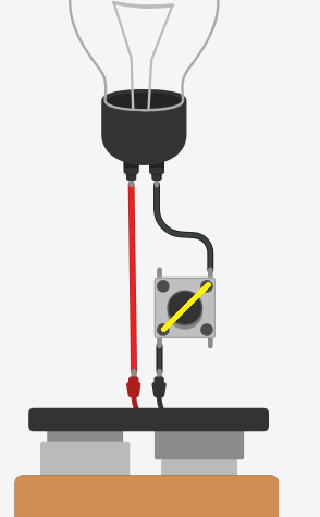
SPST Push ButtonThe pushbutton switch can separate the bulb from the battery so that the circuit is always "open" (that means it acts like it is not attached to power). In the diagram to the right, a yellow line shows the path that the electric current must pass through. It cannot pass through there unless the button is pressed. When the button is pressed, then the circuit is "closed" and the current will run from one corner of the switch to the other corner, allowing the bulb to light just like it did when the it was connected directly to the battery.
MomentaryA switch is considered to be "momentary" if it is springs back to its resting position (usually the OFF position). This particular pushbutton switch is momentary because it only works as long as you hold it down. Not all pushbutton switches are momentary. A distortion pedal for guitar is usually operated by a foot switch that alternates between on and off each time it is pressed (push-on-push-off instead of momentary).
SPSTA switch with only 2 terminals is always an SPST switch. When the switch is turned on, then both terminals are connected to each other. The pushbutton in TinkerCAD has 4 terminals (one at each corner), for the sake of convenience, however, they are actually 2 pairs of only 2 separate terminals and this makes the switch especially confusing if you rotate it. For the sake of avoiding confusion, it is HIGHLY recommended that you only use 2 terminals at a time, and ALWAYS opposite corners.
S = single P = pole T = throw So an SPST switch means there is single "pole" (or common) connection, and a single "throw" that the pole will be connected to when the button is on. |
|
AND Gate - Series
|
The AND gate is a gate that prevents a circuit from turning on unless 2 switches are pressed at the same time.
This was the concept used in the opening scene of the movie War Games when one man failed to turn his key to launch the missiles while the other man turned his own key. This concept is demonstrated with the circuit on the right. Both buttons (the left AND right) must be pressed in order for the bulb to light up. When components are chained together, heel-to-toe, such that the circuit travels from one switch to the next in a chain, then we say that they are wired in series. |

|
OR Gate - Parallel
|
The OR gate allows a circuit to turn on as long as one switch OR the other is pressed. The circuit on the right has two switches that can operate the bulb.
An example of how this may be useful is a doorbell which has a button at the front door, and a separate button at the back door. When two switches are not chained heel-to-toe, but instead a wire forks (splits like a Y) into two switches side-by-side, we say that the switches are wired in parallel. |

|
Parallel vs Series - How can you tell?
You may look at a circuit and be unsure if multiple switches are wired in series or parallel. How do you know? The simple way to answer that question is to remove one of the switches and ask "will this circuit still work? "

|
To the left is a picture of the AND- gate but with one of the switches removed. Without it, the bulb will not light up. Therefore it is wired in series because the switch is a necessary "link in the chain".
The OR-gate is shown on the right but with one of the switches removed. The bulb can still light up with the other button because the buttons were wired parallel. |

|
SPDT Slideswitch
|
A Single-Pole, Double-Throw switch has 3 terminals. The centre terminal is the "pole" or "common" and the other two are the throws. If the switch is flipped to the right, then the common will be connected to the throw on the right. If the switch is flipped to the left, then the common will be connected to the throw on the left. The flow of current for each case is shown in yellow. The two throws will NEVER come into contact with each other.
|

|
Selecting One Bulb or Another
|
The diagram on the right shows two bulbs that are powered by the same battery. A slideswitch may be inserted to select between one bulb or the other.
There are multiple ways to do this. In our example, we will put the switch onto the black wires. You can see that there are only 3 points that the black wires are connected to:
These 3 points will be re-wired to the 3 terminals on the new switch. Of the 3 points mentioned, both bulbs have the black terminal of the battery in common with each other. This give us a clue as to what should be connected to the "common" terminal of the switch. |

|
|
In the new circuit on the right, we connect the black terminal of the battery to the common pole of the switch.
The left throw of the switch is wired to the bulb on the left. The right throw of the switch is wired to the bulb on the right. A circuit like this would be useful in a chess clock which makes one clock or the other start ticking, but not both at the same time. |

|
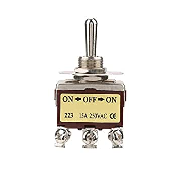
Toggle Switch
The toggle switch will not likely be used much in this course, but is common enough that it deserves some attention. It functions very similar to a slide switch, however the terminals are slightly different and there are variations of the toggle which you don't typically find on a slide switch. It is unusual for a slide switch to have more than 2 positions (double throw), however, it is not uncommon for a toggle switch to have a 3rd position. Also, though the SPDT toggle will have 3 terminals just like the SPDT slide switch, the terminals are in opposite order.

|
BOTH switches shown are flipped into the "LEFT" position. Both switches have 3 terminalss and the middle terminal is common ("pole").
The "throw" terminal on the left side of the slide switch is connected to common. However, the "throw" terminal on the toggle switch will be the opposite (right). |

|
Centre-Off
|
An SPDT switch may have 2 throws, but that doesn't always mean that it is limited to 2 positions. Sometimes an SPDT switch will have a third position that is neither left, nor right. It is the middle position that does not connect the common pole to any other terminal, so it is "off". This feature is actually more common with other types of switches which we may cover later.
|
|
Momentary & Centre-Off
|
A SPDT switch may also be momentary and have the centre off position. The common example of this is power windows on a car.
|

|
DIP Switch
|
The DIP switch is a compact switch (or group of switches) that is usually hidden at the back of a device or inside a device. It is intentionally designed to be difficult to use, so that they are not accidentally switched and are typically used only by people with proper training.
In the example on the right, a bank of 6 SPST DIP switches is shown. Though it is one unit, all 6 switches can function independently. Only the first switch is used. These switches are not as relevant to our course, but are found in TinkerCAD. |

|
Rotary Switch
|
Unlike most other switches, the rotary switch allows you to rotate to many throws.
An example of its use can be found on the channel selector of an old TV set. Today you will see rotary switches in cars to control the ventilation. |

|
