Inductors (Electromagnets)
|
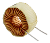
An inductor or electromagnet is a device that creates a magnetic force by running an electric current through a coil of wire.
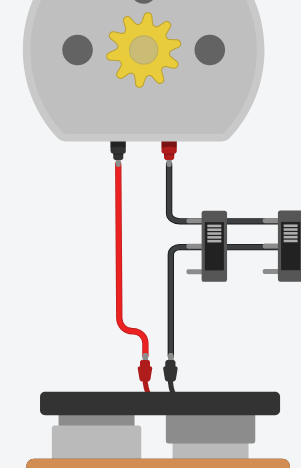
It is a key component of robotics and sets the stage for the final wiring of your robot! Consider the motor on the right. The two slide switches can turn the motor on, but wouldn't it be nice if a computer could flip those switches for us so that we don't have to? Thanks to inductors, they can! |
|
Magnet
|
|
Watch this video on how a magnet can be created with a wire wrapped around a nail and connected to a battery. This is called an electromagnet.
|
Motors
|
|
Motors are the first electromagnets that you have worked with in this course. Watch this video to see the basic concept in action.
|
Solenoids
|
|
A solenoid is a rod that moves through a coil depending on the electric current passing through.
The rod can move with enough force to hit a bell and make it ring. This is the basic concept of how a traditional doorbell works. It also provides the basis for the next component that we are going to use... the relay. |
Relays
|
|
A relay is a switch like the ones we have been using, except the switch is not activated by our fingers, it is activated by an electromagnet.
|
|
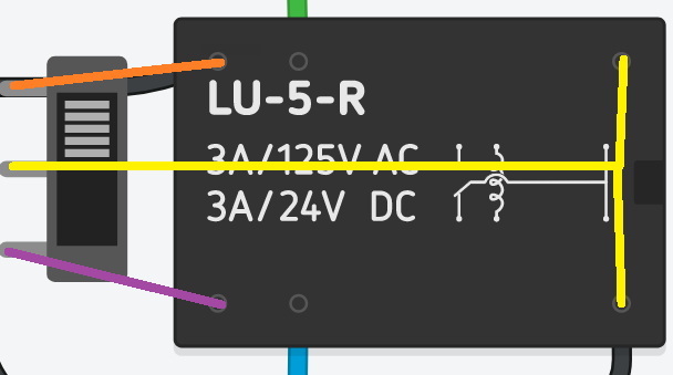
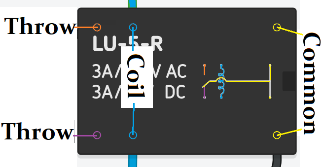
The relay on the left is shown along with the slide switch to show how the terminals correspond. The relay has 2 common poles (yellow) at one end and 2 throws (orange and purple) at the other end.
The relay on the right shows the two terminals that the coil for the electromagnet passes through. |
|
Arduino Control
Blink the LEDThe Arduino can be used to control the coil of a relay to turn things on. First, try getting an LED to light up with the blink program that is already programmed in. The built-in LED of the Arduino is also connected to pin 13. So if the LED is on, then 5V will be sent out of pin 13. We can use that to power a separate LED (see right). The "GND" pin of the Arduino is "ground" or "negative" and will connect to the other end of your LED.
|

|
Blink the Relay
|
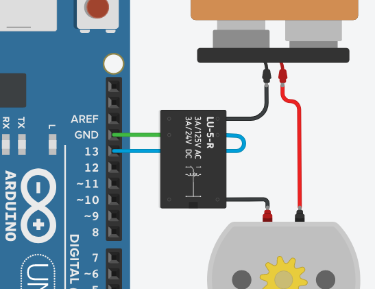
If you can get the Arduino to make an external LED blink, then you will be able to get the Arduino to trigger a relay in order to control a motor on and off.
The example on the right shows a relay with the electromagnet coil connected to pin 13 and GND of the Arduino. The Arduino will "blink" the relay on and off. The relay will connect/disconnect the 9V battery to (and from) the motor. |
|
Modular Relays
|
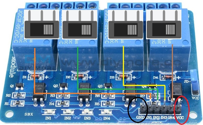
Unfortunately the type of relays available in TinkerCAD are not nearly as easy to use as the ones that we will use on our real robots in class. The ones we use in class will come in a pack of 4 (see right - modified to show slide switches), mounted on a single printed circuit board. Each of the 4 relays have 3 screw terminals (1 pole, 2 throws). Those are the terminals that will connect between the battery and the motors.
There are also 6 pins in the bottom right corner of the relay module that need to be hooked up to the Arduino. The GND pin of the relay must be connected to the GND pin on the Arduino. The next 4 pins are the controller pins which operate the relays. Those 4 pins need to be connected to 4 digital pins on the Arduino (numbered 0-13, but I recommend using pins 2-12 unless you need more). Lastly, the VCC (5V) pin of the relay must connect to 5V pin on the Arduino. |
|
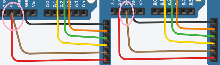
The circuit below shows how to connect the relay board to the Arduino. It will allow pins 2-5 on the Arduino to flip the 4 relays independently. However, it will do nothing until you program it to turn those pins on. Remember, this type of relay board is not currently available in TinkerCAD.
Testing
|
Testing a relay does not require a complex circuit or program. Since the relay is switched by a signal from one of the digital pins (0-13 which put out 5V), then it will also switch on if we connect it directly to the 5V pin of the Arduino which is always on. If we want to make sure that a relay is turned off, then we just need to connect it to the GND pin. This is demonstrated with the brown wire on the right which controls only the 4th relay on our module.
|
|
Normal Position
Unlike the sliding SPDT switch, a relay is a MOMENTARY switch. It will only remain flipped as long as a digital "on" signal is received. As soon as the signal is no longer "on", then the switch flips back to its original resting position. One throw will be the resting position called "normally closed" or "NC" for short. If the relay is off, then the common is connected to the NC throw. The opposite throw is "normally open" or "NO" for short. It will not be connected to common unless the relay is turned on.
Honourable Mention
The videos and info below are for the sake of your own interest, rather than being directly related to course content. Electromagnets play an important part in our music...
Speakers and Microphones
|
|
A speaker is an electromagnet connected to a cone which allows sound waves to be generated by fluctuating the electric current from an amplifier.
A microphone is actually the identical concept of a speaker, but just used in reverse. It gathers sound waves into the cone (diaphragm) which causes fluctuation in the electromagnetic coil which are sent to some sort of amplifier. The video on the left shows how to make your own speaker, but beware that there is a significant amount of science behind speakers and you should never plug any speaker (even if you buy one) into any amplifier unless you are certain their specifications match. |
Electric Guitar Pickups
|
|
The pickup on an electric guitar is not actually a microphone. It is a coil of wire that is wrapped around a magnet and the magnetic field is affected by the vibration of metal strings (which is why they don't work with nylon string guitars).
|
Speakers in Parallel vs Series
|
An amplifier is built with a specific speaker load in mind. Equipment can be damaged if you do not match the speaker properly with the amplifier. Like a resistor, speakers have resistance and are typically made with a resistance of either 4 ohm, 8 ohm, or 16 ohms. It is generally accepted practice that an amplifier will handle speakers with higher resistance than the amp was made for and it highly recommended to never go below the minimum resistance.
|
|
Attaching multiple speakers to an amplifier will affect the resistance depending on how they are wired.
If you wire speakers in series, then the total resistance load on the amp will be the sum of each speaker.
Two 8 ohm speakers wired in series would be the same as a single 16 ohm speaker.
If you wire the speakers in parallel, then the total resistance load on the amp will be reduced. The calculation is a bit complicated but usually we wire speakers in pairs, so 2 identical speakers in parallel would be HALF of the specified resistance.
Two 8 ohm speakers wired in parallel would be the same as a single 4 ohm speaker.
Guitar players often use 4 speakers that are wired with a combination of series and parallel. Using this combination, four identical 8 ohm speakers will act as an 8 ohm load on the amp.
