Mounting Circuits
|
There are multiple options for attaching and mounting circuits. Early electronics resorted to attaching wires from one component to the next (referred to as "point-to-point") like we have been doing in TinkerCAD.
Most commercial electronics are mounted and soldered on printed circuit boards (a type of plastic with copper lines etched on it instead of wires). This is an efficient way to mass-produce electronics, but is an involved process that requires chemicals and a soldering iron, so it is not ideal for the classroom. The board shown on the right is actually called a "perf-board" which has pre-drilled holes on it for convenience, but it still requires soldering. |

|
Breadboards
|
Solderless breadboards (shown right) are a quick way to organize circuits and make connections between components because they are "plug-and-play". Each hole in the breadboard is connected to several others for adding in jumper wires and making quick connections to other components.
Some breadboards have a power strip on the sides which allows you to plug in a power source like a battery. All of the holes along the red line are connected to each other and are designated for the positive connection. All of the holes along the black (sometimes blue) line are connected and are designated for negative/ground. If a power source is plugged into it, then other electronic components can draw power from this power strip.
As an example, the Arduino below is able to power up the red LED because they are both connected through the breadboard. 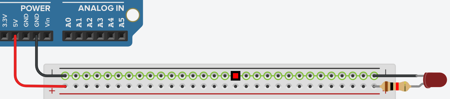
|
|
|
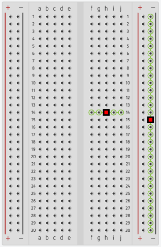
The interior of the breadboard (right) also has several rows of holes (listed by number). Each row is separated from the next.
Row 1 is not connected to row 2 etc... Each row is also split down the middle by a large trough. So that the 5 holes on the left (abcde) are not connected to the 5 holes on the right (fghij). |

|
Examples:
|
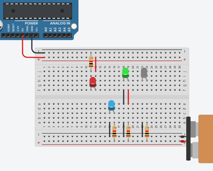
The circuit on the right has 2 different sources of power (5V from the Arduino, and 9V from a battery) and 4 LED's.
The red LED is connected to 5V. The blue LED is powered by the 9V The green LED is also powered by the 9V only because wires cross over the middle trough. The white LED does not light up like the green one because there is no connection across the trough. |
|
Jumper Wire

|
There are two types of wire that you will likely come across.
Stranded wire has several strands of wire inside of the insulation. It is
Solid wire is a single thick strand of wire inside the insulation. It is
|
